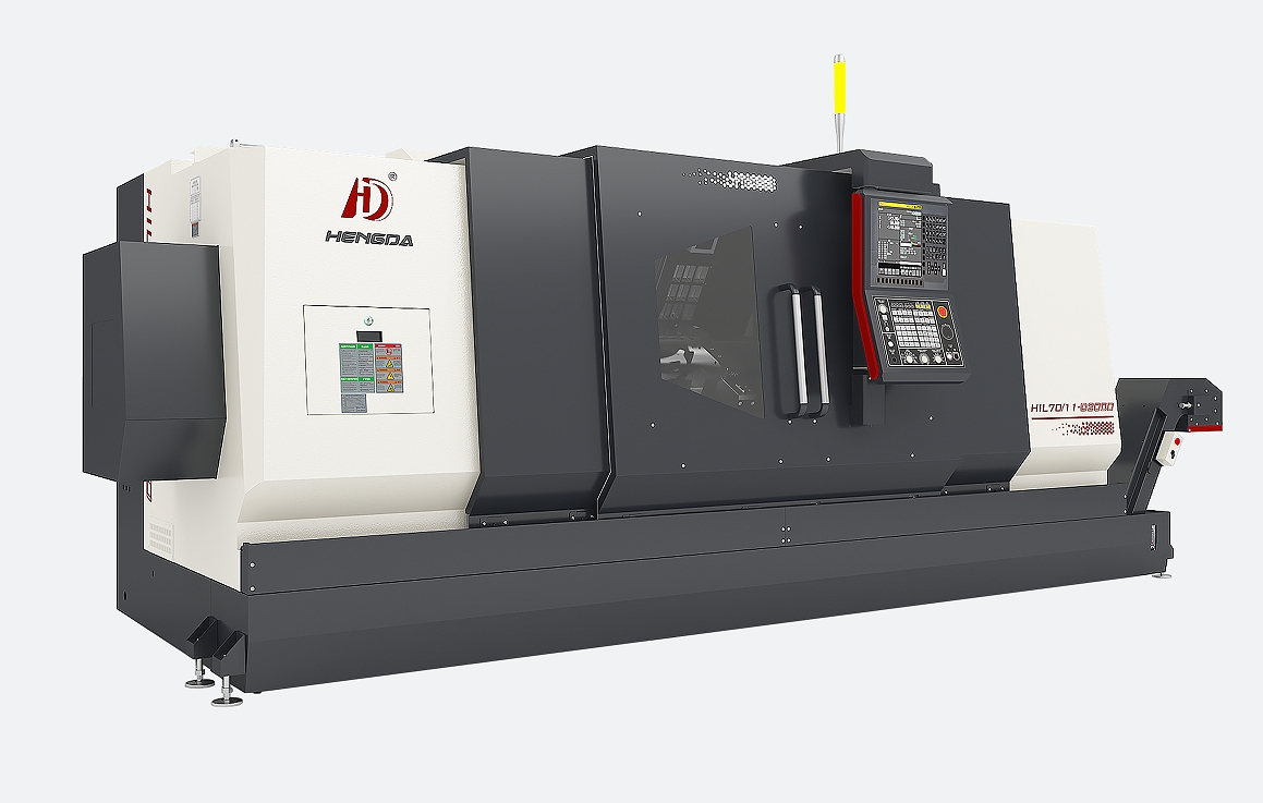
HIL70 series
CNC lathe is one of the widely used CNC machine tools. It is mainly used for cutting the inner and outer cylindrical surfaces of shaft or disc parts, inner and outer conical surfaces with arbitrary cone angles, complex rotating inner and outer surfaces, cylindrical and conical threads, and can perform groove cutting, drilling, expanding, reaming, and boring.
Keyword:
Models for China Market
Slant Bed CNC Turning Center
CNC Turn Mill
Details
Product characteristics
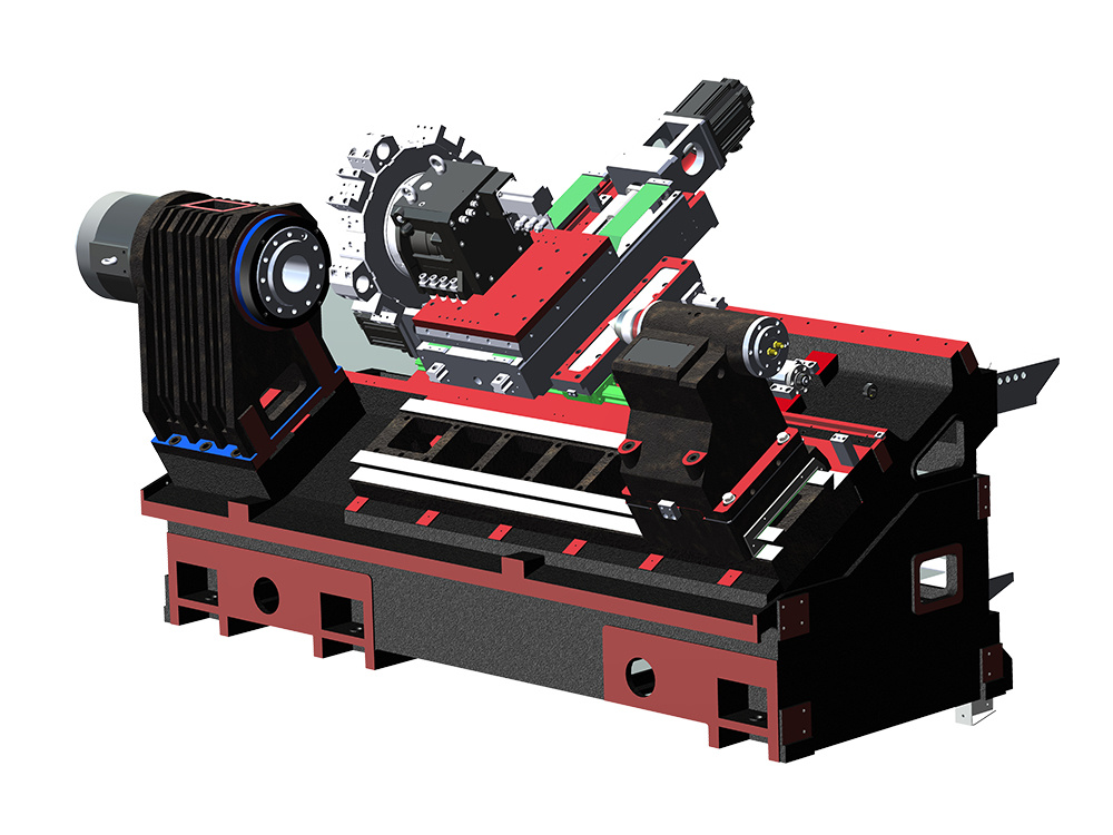
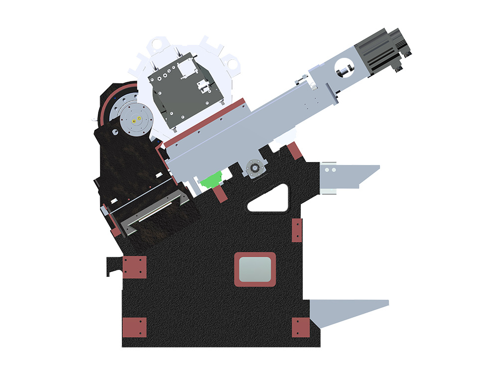
● 30° overall tilting bed design, high rigidity, strong bearing capacity, suitable for heavy chips, smooth chip removal.
● Finite element structure analysis, casting bar layout is reasonable, the force effect is good, linear guide adopts heavy six sliders, high strength design.
● The X/Y/Z/A shaft screw is pre-drawn structure, which can reduce the influence of temperature rise on the screw accuracy during processing. The oil seal is added to the screw bearing protection at both sides of the screw, and the ball screw is silent.
● The tail frame adopts V-shaped guide rail, heavy load rigidity, upper and lower layered structure, there is a micro adjustment device between the upper and lower layers, which is convenient for the tail frame center rotation center along the X axis direction, and the standard live center structure tail frame.
● HENGDA self-designed integrated permanent magnet synchronous Spindle Box, low noise, high precision, long life, high finish, constant torque output, high C-axis positioning accuracy.
● Wide range of options: such as large hollow chuck, increase spindle through hole, tool set, programmable tail seat, the second spindle can be connected at high speed.
● The machine adopts modular design, with different customer product requirements, select different functional equipment, can quickly realize the automation device to meet the needs of customers.
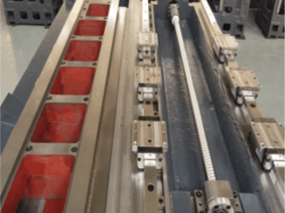
Rolling guide
High precision linear rolling guide, improve the moving speed, greatly reduce the non-cutting time. Imported ball guide rail, high positioning accuracy, less wear, can maintain accuracy for a long time, fully improve productivity, to ensure its processing stability.
30° overall tilt bed design
High-speed quiet ball screw, improve machine accuracy, ensure its processing stability, high positioning accuracy, less wear can maintain accuracy for a long time.
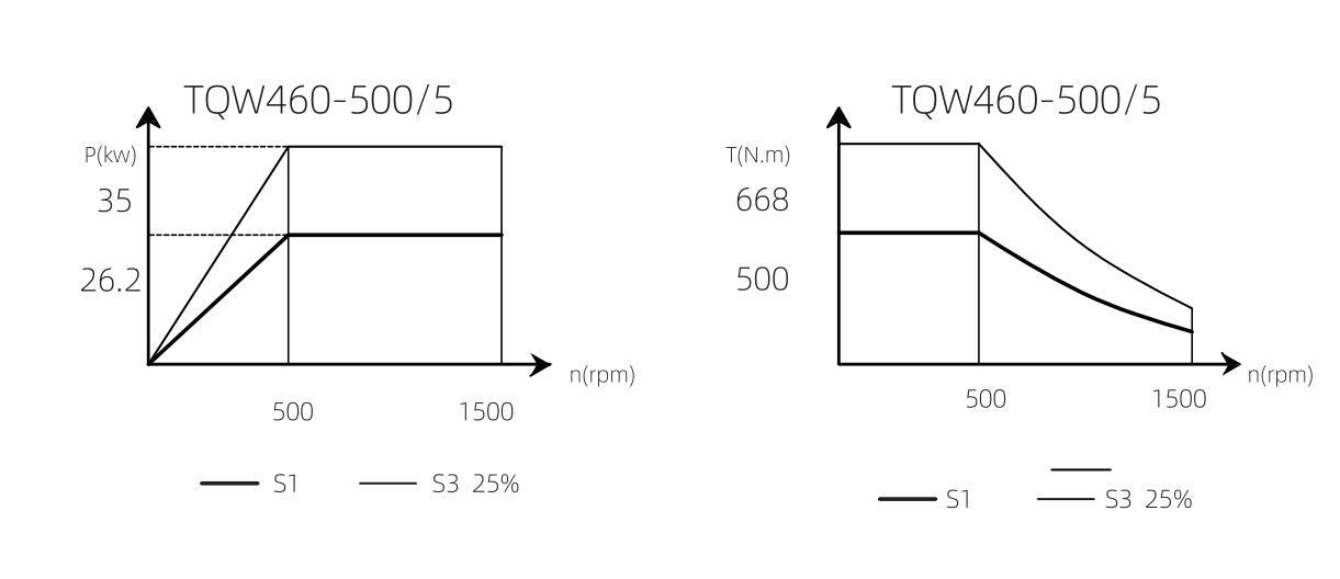
Spindle power torque diagram
Tool interferogram

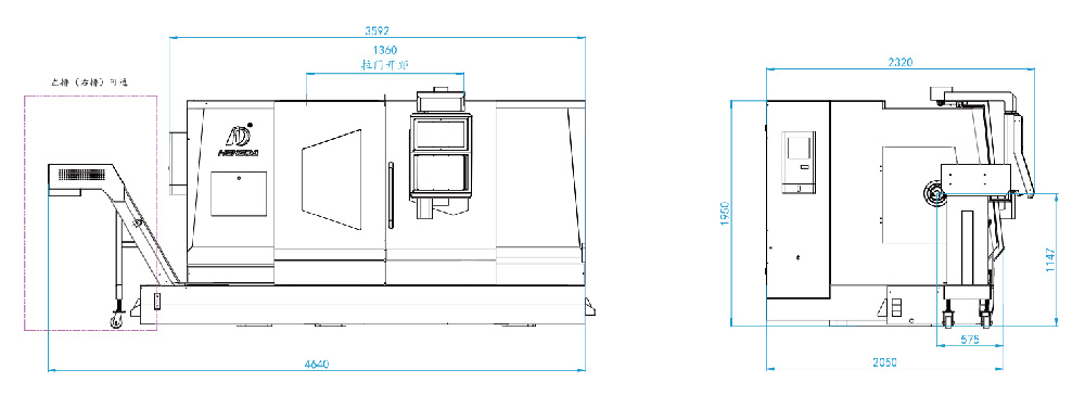
Outline dimensional drawing
| Item | Unit | HIL70/11-T1000 | HIL70/11S-T1000 | HIL70/11-D1000 | HIL70/11S-D1000 | HIL70/11-Y1000 | HIL70/11S-Y1000 | HIL70/11-T1000P | HIL70/11-D1000P | HIL70/11-Y1000P | |
| Working Capacity |
Max swing dia.over bed | mm | Φ720 | Φ720 | Φ720 | Φ720 | Φ800 | Φ800 | Φ720 | Φ720 | Φ800 |
| Max.Cutting Dia. | mm | Φ630 | Φ630 | Φ600 | Φ600 | Φ610 | Φ610 | Φ630 | Φ600 | Φ610 | |
| Max.Cutting Length | mm | 1000 | 1000 | 990 | 990 | 980 | 980 | 1000 | 990 | 980 | |
| Max.Bar dia.can pass | mm | Φ110 | Φ110 | Φ110 | Φ110 | Φ110 | Φ110 | Φ110 | Φ110 | Φ110 | |
| Spindle | Max. Spindle Speed | rpm | 1500 | 1500 | 1500 | 1500 | 1500 | 1500 | 1500 | 1500 | 1500 |
| Spindle Nose Type | ISO | A2-11 | A2-11 | A2-11 | A2-11 | A2-11 | A2-11 | A2-11 | A2-11 | A2-11 | |
| Spindle Thru-Hole Dia. | mm | Φ126 | Φ126 | Φ126 | Φ126 | Φ126 | Φ126 | Φ126 | Φ126 | Φ126 | |
| Spindle Hole Taper | Metric 135 | Metric 135 | Metric 135 | Metric 135 | Metric 135 | Metric 135 | Metric 135 | Metric 135 | Metric 135 | ||
| Distance from Spindle Center to Floor | mm | 1150 | 1150 | 1150 | 1150 | 1150 | 1150 | 1150 | 1150 | 1150 | |
| Chuck Size | Inch | Hollow 12"/Solid 15'' | Hollow 12"/Solid 15'' | Hollow 12"/Solid 15'' | Hollow 12"/Solid 15'' | Hollow 12"/Solid 15'' | Hollow 12"/Solid 15'' | Hollow 12"/Solid 15'' | Hollow 12"/Solid 15'' | Hollow 12"/Solid 15'' | |
| Spindle Motor Torque | N.m | 500 | 500 | 500 | 500 | 500 | 500 | 500 | 500 | 500 | |
| Sub-Spindle | Max. Spindle Speed | rpm | / | 2500 | / | 2500 | / | 2500 | / | / | / |
| Spindle Nose Type | ISO | / | A2-8 | / | A2-8 | / | A2-8 | / | / | / | |
| Spindle Thru-Hole Dia. | mm | / | 61 | / | 61 | / | 61 | / | / | / | |
| Spindle Hole Taper | / | 70 | / | 70 | / | 70 | / | / | / | ||
| Hydraulic Tailstock | Tailstock Sleeve dia. | mm | Φ125 | / | Φ125 | / | Φ125 | / | / | / | / |
| Tailstock Sleeve Travel | mm | 150 | / | 150 | / | 150 | / | ||||
| Taper | MT6 | / | MT6 | / | MT6 | / | / | / | / | ||
| Servo Tailstock | Tailstock Travel | mm | / | / | / | / | / | / | 1100 | 1100 | 1100 |
| Tailstock Taper | / | / | / | / | / | / | / | MT6 | MT6 | MT6 | |
| XYZA Axis Travel | X Axis Travel | mm | 315 | 315 | 315 | 315 | 315 | 315 | 315 | 315 | 315 |
| Z Axis Travel | mm | 1035 | 1035 | 1035 | 1035 | 1035 | 1035 | 1035 | 1035 | 1035 | |
| Y/A Axis Travel | mm | / | A 1100 | / | A 1100 | Y 200 | 200/1100 | A 1100 | A 1100 | 200/1100 | |
| Rapid federate(X/Z) | m/min | 20 / 20 | 20 / 20 | 20 / 20 | 20 / 20 | 20 / 20 | 20 / 20 | 20 / 20 | 20 / 20 | 20 / 20 | |
| Rapid federate(Y/A) | m/min | / | A 20 | / | A 20 | Y 15 | 15 / 20 | A 20 | A 20 | 15 / 20 | |
| Tool Turret | Tool No. | 12 | 12 | 12 | 12 | 12 | 12 | 12 | 12 | 12 | |
| Turret Type | Servo Turret | Servo Turret | Driven Turret BMT65 | Driven Turret BMT65 | Driven Turret BMT65 | Driven Turret BMT65 | Servo Turret | Driven Turret BMT65 | Driven Turret BMT65 | ||
| OD Turning Cutter Tool Holder Size | mm | 32×32 | 32×32 | 25×25 | 25×25 | 25×25 | 25×25 | 32×32 | 25×25 | 25×25 | |
| Max.Tool Holder Dia.of Boring Cutter | mm | Φ50 | Φ50 | Φ32 | Φ32 | Φ32 | Φ32 | Φ50 | Φ32 | Φ32 | |
| Accuracy | Positioning accuracy(X/Z) | mm | 0.006 | 0.006 | 0.006 | 0.006 | 0.006 | 0.006 | 0.006 | 0.006 | 0.006 |
| Positioning accuracy(Y/A) | mm | / | A 0.006 | / | A 0.006 | Y 0.008 | 0.008/0.006 | A 0.006 | A 0.006 | 0.008/0.006 | |
| Re-Positioning accuracy(X/Z) | mm | 0.004 | 0.004 | 0.004 | 0.004 | 0.004 | 0.004 | 0.004 | 0.004 | 0.004 | |
| Re-Positioning accuracy(Y/A) | mm | / | A 0.004 | / | A 0.004 | Y 0.006 | 0.006/0.004 | A 0.004 | A 0.004 | 0.006/0.004 | |
| Others | Power Requested | KVA | 40 | 60 | 46 | 66 | 48 | 68 | 44 | 50 | 52 |
| Machine Size(L×W×H) | mm | 4640×2320×2070 | 4640×2320×2070 | 4640×2320×2070 | 4640×2320×2070 | 4640×2320×2070 | 4640×2320×2070 | 4640×2320×2070 | 4640×2320×2070 | 4640×2320×2070 | |
| Machine Weight (appro.) | KG | 6900 | 7200 | 6900 | 7200 | 7100 | 7200 | 6900 | 6900 | 7100 | |
| Hydraulic Center Rest | Opt. | / | Opt. | / | Opt. | / | / | / | / | ||
| CNC Controller | KND 2000 | Std. | Std. | Std. | Std. | Std. | Std. | Std. | Std. | Std. | |
| SYNTEC | Opt. | Opt. | Opt. | Opt. | Opt. | Opt. | Opt. | Opt. | Opt. | ||
| FANUC/Siemens/Mitsubishi | Opt. | Opt. | Opt. | Opt. | Opt. | Opt. | Opt. | Opt. | Opt. | ||
| Item | Unit | HIL70/11-T2000 | HIL70/11S-T2000 | HIL70/11-D2000 | HIL70/11S-D2000 | HIL70/11-Y2000 | HIL70/11S-Y2000 | HIL70/11-T2000P | HIL70/11-D2000P | HIL70/11-Y2000P | |
| Working Capacity |
Max swing dia.over bed | mm | Φ720 | Φ720 | Φ720 | Φ720 | Φ800 | Φ800 | Φ720 | Φ720 | Φ800 |
| Max.Cutting Dia. | mm | Φ630 | Φ630 | Φ600 | Φ600 | Φ610 | Φ610 | Φ630 | Φ600 | Φ610 | |
| Max.Cutting Length | mm | 2000 | 2000 | 1990 | 1990 | 1980 | 1980 | 2000 | 1990 | 1980 | |
| Max.Bar dia.can pass | mm | Φ110 | Φ110 | Φ110 | Φ110 | Φ110 | Φ110 | Φ110 | Φ110 | Φ110 | |
| Spindle | Max. Spindle Speed | rpm | 1500 | 1500 | 1500 | 1500 | 1500 | 1500 | 1500 | 1500 | 1500 |
| Spindle Nose Type | ISO | A2-11 | A2-11 | A2-11 | A2-11 | A2-11 | A2-11 | A2-11 | A2-11 | A2-11 | |
| Spindle Thru-Hole Dia. | mm | Φ126 | Φ126 | Φ126 | Φ126 | Φ126 | Φ126 | Φ126 | Φ126 | Φ126 | |
| Spindle Hole Taper | Metric 135 | Metric 135 | Metric 135 | Metric 135 | Metric 135 | Metric 135 | Metric 135 | Metric 135 | Metric 135 | ||
| Distance from Spindle Center to Floor | mm | 1150 | 1150 | 1150 | 1150 | 1150 | 1150 | 1150 | 1150 | 1150 | |
| Chuck Size | Inch | Hollow 12"/Solid 15'' | Hollow 12"/Solid 15'' | Hollow 12"/Solid 15'' | Hollow 12"/Solid 15'' | Hollow 12"/Solid 15'' | Hollow 12"/Solid 15'' | Hollow 12"/Solid 15'' | Hollow 12"/Solid 15'' | Hollow 12"/Solid 15'' | |
| Spindle Motor Torque | N.m | 500 | 500 | 500 | 500 | 500 | 500 | 500 | 500 | 500 | |
| Sub-Spindle | Max. Spindle Speed | rpm | / | 2500 | / | 2500 | / | 2500 | / | / | / |
| Spindle Nose Type | ISO | / | A2-8 | / | A2-8 | / | A2-8 | / | / | / | |
| Spindle Thru-Hole Dia. | mm | / | 61 | / | 61 | / | 61 | / | / | / | |
| Spindle Hole Taper | / | 70 | / | 70 | / | 70 | / | / | / | ||
| Hydraulic Tailstock | Tailstock Sleeve dia. | mm | Φ125 | / | Φ125 | / | Φ125 | / | / | / | / |
| Tailstock Sleeve Travel | mm | 150 | / | 150 | / | 150 | / | ||||
| Taper | MT6 | / | MT6 | / | MT6 | / | / | / | / | ||
| Servo Tailstock | Tailstock Travel | mm | / | / | / | / | / | / | 2100 | 2100 | 2100 |
| Tailstock Taper | / | / | / | / | / | / | / | MT6 | MT6 | MT6 | |
| XYZA Axis | X Axis Travel | mm | 315 | 315 | 315 | 315 | 315 | 315 | 315 | 315 | 315 |
| Z Axis Travel | mm | 2035 | 2035 | 2035 | 2035 | 2035 | 2035 | 2035 | 2035 | 2035 | |
| Y/A Axis Travel | mm | / | A 2100 | / | A 2100 | Y 200 | 200/2100 | A 2100 | A 2100 | 200/2100 | |
| Rapid federate(X/Z) | m/min | 20 / 20 | 20 / 20 | 20 / 20 | 20 / 20 | 20 / 20 | 20 / 20 | 20 / 20 | 20 / 20 | 20 / 20 | |
| Rapid federate(Y/A) | m/min | / | A 20 | / | A 20 | Y 15 | 15 / 20 | A 20 | A 20 | 15 / 20 | |
| Tool Turret | Tool No. | 12 | 12 | 12 | 12 | 12 | 12 | 12 | 12 | 12 | |
| Turret Type | Servo Turret | Servo Turret | Driven Turret BMT65 | Driven Turret BMT65 | Driven Turret BMT65 | Driven Turret BMT65 | Servo Turret | Driven Turret BMT65 | Driven Turret BMT65 | ||
| OD Turning Cutter Tool Holder Size | mm | 32×32 | 32×32 | 25×25 | 25×25 | 25×25 | 25×25 | 32×32 | 25×25 | 25×25 | |
| Max.Tool Holder Dia.of Boring Cutter | mm | Φ50 | Φ50 | Φ32 | Φ32 | Φ32 | Φ32 | Φ50 | Φ32 | Φ32 | |
| Accuracy | Positioning accuracy(X/Z) | mm | 0.006 | 0.006 | 0.006 | 0.006 | 0.006 | 0.006 | 0.006 | 0.006 | 0.006 |
| Positioning accuracy(Y/A) | mm | / | A 0.006 | / | A 0.006 | Y 0.008 | 0.008/0.006 | A 0.006 | A 0.006 | 0.008/0.006 | |
| Re-Positioning accuracy(X/Z) | mm | 0.004 | 0.004 | 0.004 | 0.004 | 0.004 | 0.004 | 0.004 | 0.004 | 0.004 | |
| Re-Positioning accuracy(Y/A) | mm | / | A 0.004 | / | A 0.004 | Y 0.006 | 0.006/0.004 | A 0.004 | A 0.004 | 0.006/0.004 | |
| Others | Power Requested | KVA | 40 | 60 | 46 | 66 | 48 | 68 | 44 | 50 | 52 |
| Machine Size(L×W×H) | mm | 5640×2320×2070 | 5640×2320×2070 | 5640×2320×2070 | 5640×2320×2070 | 5640×2320×2070 | 5640×2320×2070 | 5640×2320×2070 | 5640×2320×2070 | 5640×2320×2070 | |
| Machine Weight (appro.) | KG | 9300 | 9600 | 9300 | 9600 | 9500 | 9800 | 9300 | 9300 | 9300 | |
| Hydraulic Center Rest | Opt. | / | Opt. | / | Opt. | / | / | / | / | ||
| CNC Controller | KND 2000 | Std. | Std. | Std. | Std. | Std. | Std. | Std. | Std. | Std. | |
| SYNTEC | Opt. | Opt. | Opt. | Opt. | Opt. | Opt. | Opt. | Opt. | Opt. | ||
| FANUC/Siemens/Mitsubishi | Opt. | Opt. | Opt. | Opt. | Opt. | Opt. | Opt. | Opt. | Opt. | ||
Note: * HIL is model for international market. HL is old model for Chinese Market.
Old Model
HL3511-T1000 HL3511S-T1000 HL3511-D1000 HL3511S-D1000 HL3511-Y1000 HL3511S-Y1000 HL3511-T1000Z HL3511-D1000Z HL3511-Y1000Z
HL3511-T2000 HL3511S-T2000 HL3511-D2000 HL3511S-D2000 HL3511-Y2000 HL3511S-Y2000 HL3511-T2000Z HL3511-D2000Z HL3511-Y2000Z
CNC lathe is one of the widely used CNC machine tools. It is mainly used for cutting the inner and outer cylindrical surfaces of shaft or disc parts, inner and outer conical surfaces with arbitrary cone angles, complex rotating inner and outer surfaces, cylindrical and conical threads, and can perform groove cutting, drilling, expanding, reaming, and boring.
Relevant information
这里是标题一h1占位文字
LEAVE US
A MESSAGE
